SPI
串行外设接口
Serial Peripheral Interface (SPI) devices are typically found where fast data transfer rates are required. SPI is well suited for high-bandwidth use cases such as external non-volatile memory and graphical displays. Many sensor devices support SPI in addition to I2C.
串行外设接口(SPI)设备通常被用于需要快速数据传输的工作场合。尤其适合需要高带宽的使用场景,例如外部非易失性存储器(NVM)和图形显示器。许多传感器设备除了支持I2C以外也支持SPI。
SPI is a synchronous serial interface, which means it relies on a shared clock signal to synchronize data transfer between devices. A master device controls the triggering of the clock signal and all other connected peripherals are known as slaves. Each device is connected to the same set of data signals to form a bus.
SPI是 同步 串行接口,这意味着设备之间依赖于共享的时钟信号来对数据传输进行同步。主设备控制着时钟信号的触发,其他所有连接的外部设备都被认为是 从设备 。每个设备都连接到相同的数据信号集而形成 总线 。
Theoretically, the data transfer rate for SPI is only limited by how fast the master can toggle the clock signal. Clock speeds are typically in the 16MHz to 25MHz range. This high-speed shared clock allows SPI peripherals to transfer data more quickly and with fewer errors than UART.
SPI总线的理论传输速度仅受到主设备切换时钟信号快慢的限制。通常时钟速度在16MHz到25MHz的范围内。这类高速共享的时钟可以允许SPI外设比UART设备传输速率更快且错误率更低。
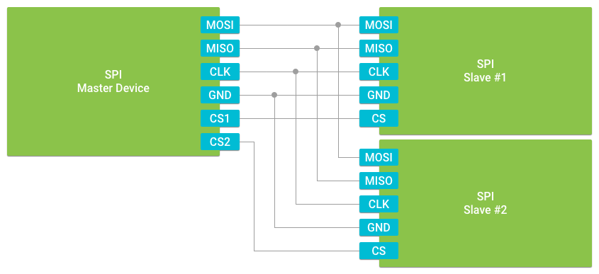
SPI supports full-duplex data transfer, meaning the master and slave can simultaneously exchange information. To support full-duplex transfer, the bus must provide the following separate signals, which makes SPI a minimum 4-Wire interface:
SPI支持 全双工 数据传输,意味着主从设备之间可以连续不断的进行信息交换。为了能支持全双工传输,总线接口最少必须提供以下四根单独的信号接线:
- Master Out Slave In (MOSI)
- Master In Slave Out (MISO)
- Shared clock signal (CLK)
Common ground reference (GND)
主入从出(MISO)
- 共享时钟信号(CLK)
- 共用参考地线(GND)
SPI supports multiple slave devices connected along the same bus. Unlike I2C, slave devices are addressed using hardware. An external chip select signal is required for each slave to allow the master to address that particular device as the data transfer target. This signal is not necessary if only using a single slave.
SPI支持同时将多个从设备连接在同一总线上。与I2C的连接方式区别在于,从设备的寻址采用硬件方式。每个从设备都需要连接外部 片选 信号到主设备用于寻址到该设备进行数据传输。只有在总线上只接一个从设备的时候可以不接片选信号。
Managing the device connection
管理设备连接
In order to open a connection to a particular SPI slave, you need to know the unique name of the bus. During the initial stages of development, or when porting an app to new hardware, it is helpful to discover all the available device names from PeripheralManagerService using getSpiBusList():
当需要建立访问某从设备的连接时,您需要获知总线的唯一名称。在发开的早期阶段,或者当您在将应用移植到某个新硬件的时候,您可以通过由PeripheralManagerService提供的getSpiBusList()来发现所有可用的设备名称:
PeripheralManagerService manager = new PeripheralManagerService();List<String> deviceList = manager.getSpiBusList();if (deviceList.isEmpty()) {Log.i(TAG, "No SPI bus available on this device.");}else {Log.i(TAG, "List of available devices: " + deviceList);}
SPI controllers that support multiple hardware chip selects will report each available slave port as a separate device name. For example, a board that supports CS0, CS1, and CS2 on the same SPI bus will return names similar to "SPI0.0", "SPI0.1", and "SPI0.2" from getSpiBusList().
支持多个硬件片选的SPI控制器将把每一个从端口当做一个独立的设备名来汇报。例如在一块支持将CS0, CS1, 和CS2连到同一个SPI总线上的板子上,getSpiBusList()将返回形如"SPI0.0", "SPI0.1", 和"SPI0.2"的设备名称。
Once you know the target name, use PeripheralManagerService to connect to that device. When you are done communicating with the peripheral device, close the connection to free up resources. Additionally, you cannot open a new connection to the device until the existing connection is closed. To close the connection, use the device’s close() method.
当您取得目标设备名称后,使用PeripheralManagerService去连接该设备。当您和该外设的通信结束后,请记得及时关闭连接以便释放相关资源。另外请注意,在已有连接的情况下,您无法再建立对该设备的新连接了。如需关闭连接,调用该设备的close()方法。
public class HomeActivity extends Activity {// SPI Device Nameprivate static final String SPI_DEVICE_NAME = ...;private SpiDevice mDevice;@Overrideprotected void onCreate(Bundle savedInstanceState) {super.onCreate(savedInstanceState);// Attempt to access the SPI devicetry {PeripheralManagerService manager = new PeripheralManagerService();mDevice = manager.openSpiDevice(SPI_DEVICE_NAME);} catch (IOException e) {Log.w(TAG, "Unable to access SPI device", e);}}@Overrideprotected void onDestroy() {super.onDestroy();if (mDevice != null) {try {mDevice.close();mDevice = null;} catch (IOException e) {Log.w(TAG, "Unable to close SPI device", e);}}}}
Configuring clock and data modes
配置时钟和数据模式
After a connection is established with the SPI bus, configure the data transfer rate and operation modes to match the slave devices on the same bus. For data transfer to be successful, all devices on the bus must expect the same clock and data format behavior.
在于SPI总线的连接建立之后,接下来需要配置数据传输速率和操作模式用以匹配连接到该总线上的从设备。为了保证数据能够成功的传输,所有连接到该SPI总线上的设备都应该工作在相同的时钟频率并保持数据格式一致性。
Note: Some slave devices cannot configure their SPI operation mode, so refer to the documentation for your hardware when choosing peripheral devices.
注意: 有些从设备无法配置SPI的操作模式,所以当连接外设时请先请查阅您设备硬件的相关文档。
Set the SPI mode, which defines the polarity and phase of the clock signal. The mode you choose is based on three attributes:
设置SPI模式,定义时钟信号的极性和相位。您可选择的模式基于三种属性:

Idle Level: Level of the clock signal (low or high) when no data is being transferred.
空闲电平:当总线空闲时的时钟信号电平(低或高)。
Leading Edge: Front edge of each clock pulse.
采样前沿:每次时钟脉冲跳变的前沿。
Trailing Edge: Transition opposite the leading edge in each clock pulse.
采样后沿:与每次时钟脉冲跳变相反的后沿。
The following modes are supported:
支持的模式有以下几种:
MODE0- Clock signal idles low, data is transferred on the leading clock edge模式0- 时钟信号的空闲电平为低电平,数据在采样前沿进行传输MODE1- Clock signal idles low, data is transferred on the trailing clock edge模式1- 时钟信号的空闲电平为低电平,数据在采样后沿进行传输MODE2- Clock signal idles high, data is transferred on the leading clock edge模式2- 时钟信号的空闲电平为高电平,数据在采样前沿进行传输MODE3- Clock signal idles high, data is transferred on the trailing clock edge模式3- 时钟信号的空闲电平为高电平,数据在采样后沿进行传输
Set the following
SpiDeviceparameters:配置如下的
SpiDevice参数:Frequency - Specifies the shared clock signal in Hz. Clock signal capabilities will vary across device hardware. You should verify the supported frequencies of your particular device before setting this value.
频率 - 指定共享时钟信号的周期(单位为Hz)。不同设备硬件对于时钟信号的处理能力有所不同,所以您在设置您特定外设的时钟频率时,应该确认硬件上是否支持。
Justification - Specifies the ordering of the individual bits in each byte as they are transferred across the bus. This is also known as the endianness of the data. By default, data will be sent with the most significant bit (MSB) first.
对齐 - 指定在总线上传输的每个字节的每一个位的顺序,这又被称为数据传输的字节序。默认的是按照最高有效位(MSB)优先的字节序进行传输。
Bits per Word - Configures the number of bits transferred at a time in between toggling the chip select line for the given slave. The default value is 8 bits per word.
每字位数 - 用于配置每次片选信号切换到指定从设备时传输的字节数。默认为8位每字。
The following code configures the SPI connection with Mode 0, 16MHz clock, 8 bits per word, and MSB first:
以下的代码配置了SPI连接工作在模式0下,设备时钟周期16MHz,8个比特每个字,最高有效位(MSB)优先:
public void configureSpiDevice(SpiDevice device) throws IOException {// Low clock, leading edge transferdevice.setMode(SpiDevice.MODE0);device.setFrequency(16000000); // 16MHzdevice.setBitsPerWord(8); // 8 BPWdevice.setBitJustification(false); // MSB first}
Transferring data
传输数据
SPI supports both half-duplex and full-duplex data transfer. Most apps should use the half-duplex write() or read() methods to exchange data with a slave device.
SPI支持半双工和全双工数据传输。大部分应用程序应该使用半双工模式下的write()或read()方法来与从设备进行数据交换。
// Half-duplex data transferpublicvoid sendCommand(SpiDevice device, byte[] buffer) throws IOException {// Shift data out to slavedevice.write(buffer, buffer.length);// Read the responsebyte[] response = new byte[32];device.read(response, response.length);...}
To perform a full-duplex exchange, use the transfer() method instead. This method accepts two buffers for read and write. The write buffer contains data to send to the slave, while the read buffer is empty and accepts data from the slave.
要进行全双工数据交换,应改用transfer()方法。这个方法能接受读和写的两个缓冲。写缓冲包含需要发给从设备的数据,同时为空的读缓冲用于接受来自于从设备发来的数据。
The data length must be less than or equal to the smallest buffer’s size. It is common with full-duplex transfers for the buffer sizes to be equal.
数据长度必须要小于等于最小缓冲的大小。在全双工传输中经常将两端的缓冲设置成一样的大小。
// Full-duplex data transferpublicvoid sendCommand(SpiDevice device, byte[] buffer) throws IOException {byte[] response = new byte[buffer.length];device.transfer(buffer, response, buffer.length);...}

若有收获,就点个赞吧
0 人点赞
