Pico Pro Maker Kit
Follow these instructions to set up your Pico Pro Maker Kit.
Pico Pro 开发者套件
按照以下教程设置您的Pico Pro 开发者套件.
What’s in the box
Open the box and make sure you have all of the components in the kit. You will also need a small Phillips screwdriver (not provided).
Note: Some versions of the Pico Pro Maker Kit do not include the Rainbow HAT, camera, and/or multi-touch display. The full kit is shown below.
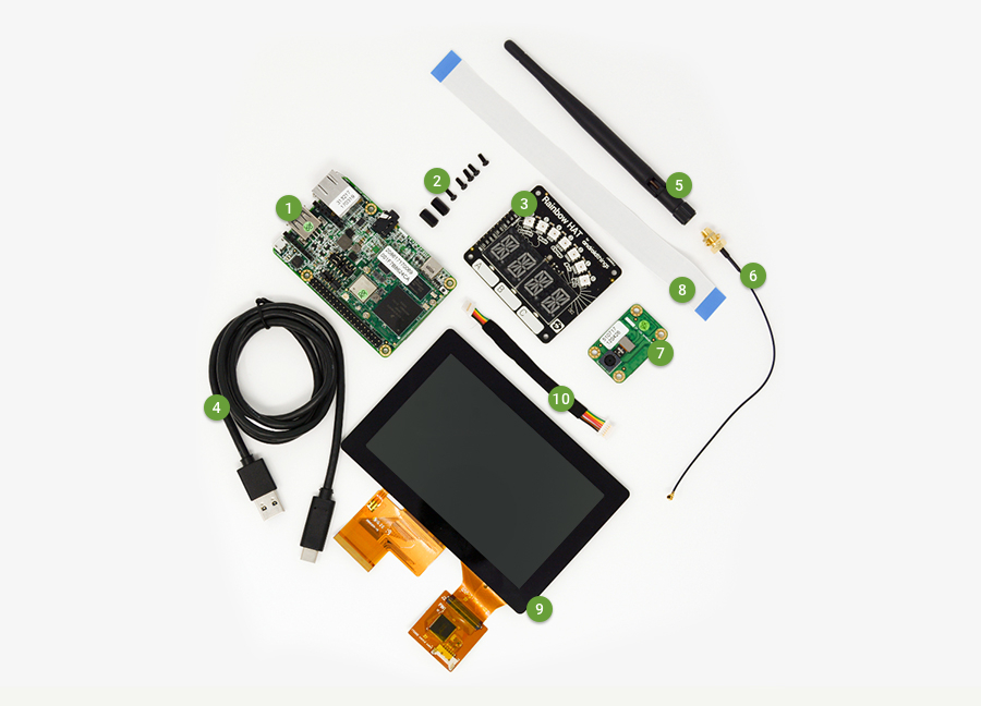
 Pico i.MX7Dual development board
|
 Standoffs (x2) and screws (x5) for the Rainbow HAT
 |
 Rainbow HAT
|
 USB-C cable
|
 Wifi antenna
|
 Antenna extender cable
 |
 Camera module
|
 Camera module cable
 |
 5” multi-touch display
|
 Display 6-wire cable
|
套件包含内容
打开包装后请先确认所有部件齐全。另外您还需要有一把小型十字镙丝刀(套件中不含此工具)。
注意: 某些版本的 Pico Pro 开发者套件不包含彩虹外接调试板, 摄像头, 或者多点触摸屏。完整套件如下图所示。
|
Pico i.MX7Dual 开发板
|
彩虹外接调试板的 2个支架 和 5颗镙丝 |
|
彩虹外接调试板 |
USB-C 数据线 |
|
Wifi 天线 |
天线延长线 |
|
摄像头模组 |
摄像头模组排线 |
|
5寸多点触摸屏 |
6线显示屏排线 |
Connect the parts
Connect the parts in the following order. Note that some versions of the Pico Pro Maker Kit do not include the Rainbow HAT, camera, and/or multi-touch display.
组装各个部件
按照以下步骤连接各个部件。注意某些版本的 Pico Pro 开发者套件不包含彩虹外接调试板,摄像头,及多点触摸屏。
Wifi antenna
Connect the wifi antenna to the development board:
 ① Locate the wifi antenna and extender cable. Screw the cable into the base of the antenna.
 |
 ② Locate the round antenna pin on the development board (pictured above). Press the small round connector at the end of the extender cable onto this pin.
 |
Wifi 天线
将 Wifi 天线连接到开发板上:
|
①固定 Wifi 天线和延长线,将 Wifi 天线延长线连接至 Wifi 天线底部并拧紧。 |
② 如图所示,在开发板上,找到圆形的天线接触点。 将延长线一端的圆形连接器固定到触点上。 |
Camera
Connect the camera to the development board:
 ① Locate the camera module and cable. Turn the board over to reveal a white connector near the edge of the board. Swivel the black retaining clip upward. Insert one end of the camera module cable into the white connector. The silver pins on the cable should be facing down. Swivel the retaining clip back down to hold the cable in place.
 |
 ② Turn over the camera module to reveal a white connector near the edge of the board. Swivel the black retaining clip upward. Insert one end of the camera module cable into the white connector. The silver pins on the cable should be facing down. Swivel the retaining clip back down to hold the cable in place.
 |
摄像头
将摄像头连接到开发板上:
|
①固定摄像头模组和数据线。将开发板翻过来可以在板子的边缘看到白色的连接器。向上旋起黑色固定卡子。将摄像头模组排线的一端插入白色连接器中。排线上的银色插销应该朝下摁入连接器。然后将固定卡子按回原位,以保证排线卡到位。 |
②翻转摄像头模组,露出靠近板子边缘的白色连接器。向上旋起黑色固定卡子。将摄像头模组排线的一端插入白色连接器中。排线上的银色插销应该朝下摁入连接器。然后将固定卡子按回原位,以保证排线卡到位。 |
Rainbow HAT
Connect the Rainbow HAT to the development board:
 ① Locate the standoffs and screws. Screw the standoffs into the two holes on the development board (pictured above). One hole is located near the USB-C connector; the other hole is located next to the audio connector.
 |
 ② Locate the Rainbow HAT and turn it over. The HAT has a 40-pin female connector. The development board has a 40-pin male connector. You will connect these together in the next step.
 |
 ③ Gently press the connector on the back of the Rainbow HAT onto the connector on the development board. Be sure to press straight down. Note that the HAT should not come in contact with the development board, especially the small, square system on a module (SoM) board attached to the main board.
 |
 ④ Use two screws to secure the standoffs to the Rainbow HAT.
 |
彩虹外接调试板
将彩虹外接调试板连接到开发板上:
|
① 定位支架和镙丝。如上图所示,用两颗镙丝将支架固定在开发板上。一个镙丝孔在USB-C连接器旁边;另一个镙丝孔在音频连接器旁边。 |
②将彩虹外接调板翻过来,调试板有一个40针脚的母连接器。 开发板上有一个40针脚的公连接器。 您将在下一步中将它们连接在一起。 |
|
③轻轻按下彩虹外接调试板背面的连接器到开发板上的连接器上。一定要垂直按下。 请注意,调试板不应与开发板接触,特别要注意在主板上的那块小的方形模块板子。 |
④使用两个镙丝将支架固定在彩虹外接调试板上。 |
Multi-touch display
Connect the display to the development board:
Note: For illustrative purposes, the connected camera module is not pictured in the following images.
 ① Locate the i.MX7Dual development board. Turn it over to reveal a white connector near the center of the board. Swivel the black retaining clip upward.
 |
 ② Locate the multi-touch display and turn it over. The display has a flat ribbon cable connected to it; you may need to remove some tape securing it to the back of the display. Insert the flat ribbon cable into the white connector on the board. Swivel the retaining clip back down to hold the cable in place.
 |
 ③ Locate the 6-wire cable for the display. Insert one end of the cable into the connector perpendicular to the ribbon cable connector. The gold contacts on the cable should be facing up.
 |
 ④ Turn both the display and the development board over. The display has a 6-wire connector; you may need to remove some tape securing it to the back of the display. Connect the remaining end of the 6-wire cable to this connector. The gold contacts on the cable should be facing up. Note that you will need to twist the 6-wire cable slightly.
 |
多点触摸显示屏
将触摸显示屏连接到开发板上:
注意: 为了便于说明,已经连接好的摄像头模组没有出现在以下演示图片中。
|
①拿起i.MX7Dual开发板。把它翻过来,露出板子中央附近的白色连接器。 向上旋起黑色固定卡子。 |
②拿起多点触摸显示屏并把它翻过来。显示器有一条连接到它的扁平带状排线;您可能需要用一些胶带把排线固定到显示器的背面。将扁平带状排线插入板上的白色连接器中。将固定卡子按回原位,以保持排线连接到位。 |
|
③找到显示器的6线排线。 排线上的金触点朝上,将排线的一端垂直于排线连接器并插入。 |
④将显示和开发板一起翻转过来。显示屏上有一个6线连接器;您可能需要使用一些胶带将排线固定到显示器背面。连接6线排线的另外一端插入此连接器。排线上的金触点应该朝上。注意,您需要非常小心地旋转6线排线,防止排线断裂。 |
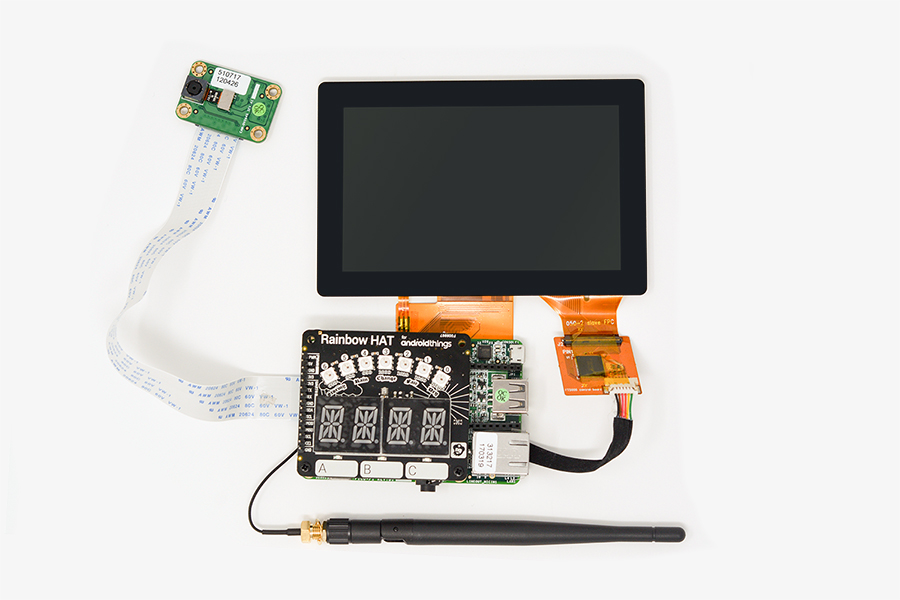
Final result
Your kit is now assembled. You will connect the USB-C cable when you flash Android Things on your board.
最终完成
您的开发套件已经组装完毕。您需要用 USB-C 数据线连接主板这样就可以烧写 Android Things 程序。
Install Android Things
Follow the hardware setup instructions to flash the latest version of Android Things on your i.MX7D development board.
安装 Android Things
按照硬件设定 教程 烧写最新版本的 Android Things 程序到您的 i.MX7D 开发板中。
Blink an LED
If you have a Rainbow HAT, follow these instructions to download and run a sample that blinks one of the HAT’s LEDs. If you don’t have a Rainbow HAT, you can connect an LED and button to the development board and run the sample.
Download and unzip the sample-button project to the directory of your choice.
Run the project using either of the following:
In Android Studio, select File > Open and select the directory where you unzipped the sample. Select Run > Run ‘app’.
From the command line:
cd sample-button-master./gradlew assembleDebugadb install -g -r app/build/outputs/apk/app-debug.apkadb shell am start com.example.androidthings.button/.ButtonActivity
Press the “A” button on the Rainbow HAT and the red LED will light up. If you connected an external button and LED, press the button to light the LED.
点亮 LED
如果您有一块彩虹外接调试板,按照以下步骤写入并启动一个例子程序 该例子可以点亮调试板上的一个LED灯。 如果您没有彩虹外接调试板,您可以参考例子连接LED和按钮 来开发调试此例子程序。
下载并解压按钮例程 到您指定的工程目录下。
按照以下步骤启动工程:
在 Android Studio 中,选择 文件 > 打开 并选择您刚才解压路径。 选择 启动 > 启动 ‘应用’.
或者以命令行方式开启:
cd sample-button-master./gradlew assembleDebugadb install -g -r app/build/outputs/apk/app-debug.apkadb shell am start com.example.androidthings.button/.ButtonActivity
按住彩虹外接调试板上的 “A” 按钮 此时红色LED灯会亮起。如果您连接了外接按钮和LED,按下按钮就会点亮 LED.
Next steps
Try one of the other code samples. Remember to uninstall any existing samples from the development board before installing a new one, so that one does not interfere with the other. For example, to uninstall the previous samples from the command line:
adb uninstall com.example.androidthings.button
Take a look at the Peripherals codelab or learn how to build your first device.
Connect with the community at g.co/iotdev.
下一步
试试 其他例程. 请注意记得先卸载并删除开发板上已经安装的例子程序,然后在安装新的例子程序,以防止程序间互相干扰。比如,可以通过类似下面的命令行卸载已经安装的程序:
adb uninstall com.example.androidthings.button
前往g.co/iotdev社区进行交流讨论.
Troubleshooting
Some USB ports don’t provide enough power for the development board. If your board will not boot (or reboot) after some time, try using a powered USB hub or a USB 3.0 port.
If you are using a native USB-C port on your host machine and the development board keeps rebooting, you may need to use a USB-A port on your host machine instead. You will need a USB-A to USB-C adapter cable.
You can report bugs and suggest new features with the Android Things issue tracker.
常见故障及排除
有些USB端口不能为开发板提供足够的电压。如果您的主板在一段时间后不能启动(或重新启动),请尝试使用电源USB集线器或支持USB 3.0的端口。
如果您使用的是在您的主机的USB-C端口但开发板不停重启,您可能需要使用您主机的USB-A端口。您将需要一个USB-A到USB-C转换线。

若有收获,就点个赞吧
0 人点赞
