Raspberry Pi 3
Raspberry Pi 3
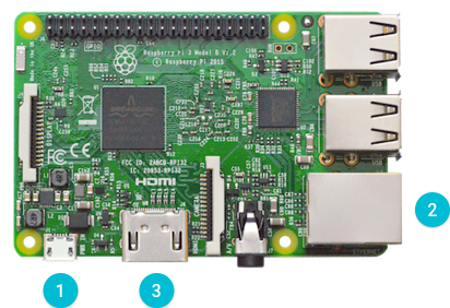
Raspberry Pi 3 Model B is the latest iteration of the world’s most popular single board computer. It provides a quad-core 64-bit ARM Cortex-A53 CPU running at 1.2GHz, four USB 2.0 ports, wired and wireless networking, HDMI and composite video output, and a 40-pin GPIO connector for physical interfacing projects.
Raspberry Pi 3B 型是这个全世界最受欢迎单片计算机系列的最新型号。它有一个四核64位 ARM Cortex-A53 1.2GHz 处理器、四个 USB 2.0 接口、支持有线和无线网络、HDMI口和复合端子输出、以及用来连接外界交互设备的一个40针的 GPIO 接口

See Raspberry Pi I/O for more details on the Peripheral I/O signals on this board.
参照 Raspberry Pi I/O 获取更多此板 外围 I/O 的信息
Flashing the image
在开发板上烧录程序镜像
Before you begin flashing, you will need the following items in addition to your Raspberry Pi:
在开始烧录之前,除了 Raspberry Pi 以外,您还需要以下设备
HDMI cable
HDMI 线
HDMI-enabled display
支持 HDMI 的显示器
Micro-USB cable
Micro-USB 线
Ethernet cable
网线
MicroSD card reader
MicroSD 读卡器
To flash Android Things onto your board, download the latest preview image in the Android Things Console (see the release notes) and follow these steps:
为了在板上烧录 Android Things ,请从 Android Things 控制台 下载最新的预览版镜像 (参见 更新注释 然后参照以下步骤:
Insert an 8 GB or larger microSD card into your development computer. 在您的用于开发的电脑上插入 8 GB 或更大的 microSD 卡
Unzip the downloaded image archive on your development computer. Navigate to the unzipped image file. 解压缩您的电脑上下载的镜像。找到解压缩镜像的文件。
Note: The compressed image file expands to over 4GB. This can cause problems for the built-in tools on some platforms. If you are unable to unzip the archive, or see a message stating that it’s corrupt, use 7-Zip (Windows) or The Unarchiver (Mac OS) instead.
注意 压缩文件解压后会超过 4 GB 。这可能导致一些平台上内置的解压缩工具出现问题。如果内置工具不能解压文件,或者工具崩溃,可以尝试 7-Zip (Windows) 或者 The Unarchiver (Mac OS)
- Follow the official Raspberry Pi instructions for writing the image to the SD card: 按照以下官方 Raspberry Pi 指南将镜像写入 SD 卡:
Insert the flashed microSD card into your board. 将烧录好的 microSD 卡插入到您的开发板中
Make the following connections to your board: 按照以下指南连接开发板上的接口
Connect a USB cable to J1 for power. 将 USB 线和 J1 口相连用来供电
Connect an Ethernet cable to your local network. 将网线连到您的本地网络
Note: If you do not have wired access to your local network, you can do either of the following:
注意: 如果您没有有线网络,您可以从以下操作中任选其一:
Connect the Ethernet cable to your development computer and assign the Raspberry Pi an IP address using DHCP.
将网线连接到您的电脑上并通过 DHCP 给 Raspberry Pi 分配一个 IP 地址
Connect a serial cable from the Raspberry Pi to your development computer. Use a serial console to connect to Wi-Fi.
Connect an HDMI cable to an external display. 将 HDMI 线连接到外置屏幕
Verify that Android is running on the device. The Android Things Launcher shows information about the board on the display, including the IP address. 确认设备 Android 系统运行正常。 Android Things 启动器在屏幕上显示包含 IP 地址在内的关于开发板的信息。
Connect to this IP address using the adb tool:
$ adb connect
connected to :5555 使用 adb 工具 连接到以下 IP 地址:
$ adb connect
connected to :5555
Note: Raspberry Pi broadcasts the hostname Android.local over Multicast DNS. If your host platform supports MDNS, you can also connect to the board using the following command:
注意: Raspberry Pi 会覆盖组播 DNS 传输主机名称 Android.local 。如果您的寄存平台支持 MDNS,您也可以通过以下操作连接开发板:
$ adb connect Android.local
Connecting Wi-Fi
连接 Wi-Fi
After flashing your board, it is strongly recommended to connect it to the internet. This allows your device to deliver crash reports and receive updates.
在烧录完您的开发板之后,强烈推荐将它连上网。这可以让您的设备发送崩溃报告和获取更新。
Note: The device doesn’t need to be on the same network as your computer.
注意: 您的设备不必和您的电脑使用相同的网络。
To connect your board to Wi-Fi, first access a shell prompt on the device. You can use either of the following methods:
为了将您的开发板连到 Wi-Fi ,首先访问设备上的 shell prompt 。您可以从以下操作中任选其一:
Connect your board to your Wi-Fi router or development computer to assign it an IP address. Run the
adb connect <ip-address>command to connect to this IP address using the adb tool. Open a shell over adb with theadb shellcommand.通过将开发板和无线路由器或者电脑相连给开发板分配 IP 地址。使用 adb 工具,运行
adb connect <ip-address>命令连接到 IP 地址。用adb shell命令打开一个 adb shell 。Connect to the serial console.
连接到 串行控制台。
Once you can access a shell prompt, follow these steps: 通过 Shell 命令行界面,参照以下步骤执行:
Send an intent to the Wi-Fi service that includes the SSID of your local network. Your board must support the network protocol and frequency band of the wireless network in order to establish a connection.
向 Wi-Fi 服务发送带有您的本地网络 SSID 的请求。您的 开发板 必须支持无线网络协议和无线网络频段以建立连接。
$ am startservice \ -n com.google.wifisetup/.WifiSetupService \ -a WifiSetupService.Connect
The following arguments are supported with this command:
此命令支持以下参数:
| Argument 参数 | Description 具体细节 |
|---|---|
-e ssid <var>network_ssid</var> |
Connect to the wireless network SSID specified by networkssid. _This argument is required. 连接到由 network_ssid 指定的无线网络 SSID 。此参数为必须参数 |
-e passphrase <var>network_pass</var> |
Optional argument to use the passcode specified by network_pass to connect to the network SSID. This argument is not necessary if your network doesn’t require a passcode. 可选参数,通过 network_pass 指定的密码来连接网络 SSID 。如果您的网络不需要密码,无需添加此参数。 |
-e passphrase64 <var>encoded_pass</var> |
Optional argument used in place of passphrase for passcodes with special characters (space, !, ", $, &, ', (, ), ;, <, >,, or |). Use [base64 encoding](https://www.base64encode.org/) to specify the value for <var>encoded_pass</var>.
可选参数,设置密码passphrase可用特殊字符 (space, !, “, $, &, ‘, (, ), ;, <, >, , or |)。使用 base64 encoding 来指定 encoded_pass 的值 |
--ez hidden true |
Optional argument to indicate that the SSID specified in this command is hidden. If omitted, this value defaults to false. 可选参数,用来表明此命令中的 SSID 不可见。如果省略,此值会被默认为 false |
Verify that the connection was successful through
logcat:$ logcat -d | grep Wifi...V WifiWatcher: Network state changed to CONNECTEDV WifiWatcher: SSID changed: ...I WifiConfigurator: Successfully connected to ...
通过
logcat确认连接成功:$ logcat -d | grep Wifi...V WifiWatcher: Network state changed to CONNECTEDV WifiWatcher: SSID changed: ...I WifiConfigurator: Successfully connected to ...
Test that you can access a remote IP address:
$ ping 8.8.8.8PING 8.8.8.8 (8.8.8.8) 56(84) bytes of data.64 bytes from 8.8.8.8: icmp_seq=1 ttl=57 time=6.67 ms64 bytes from 8.8.8.8: icmp_seq=2 ttl=57 time=55.5 ms64 bytes from 8.8.8.8: icmp_seq=3 ttl=57 time=23.0 ms64 bytes from 8.8.8.8: icmp_seq=4 ttl=57 time=245 ms
测试您可以访问远程 IP 地址:
$ ping 8.8.8.8PING 8.8.8.8 (8.8.8.8) 56(84) bytes of data.64 bytes from 8.8.8.8: icmp_seq=1 ttl=57 time=6.67 ms64 bytes from 8.8.8.8: icmp_seq=2 ttl=57 time=55.5 ms64 bytes from 8.8.8.8: icmp_seq=3 ttl=57 time=23.0 ms64 bytes from 8.8.8.8: icmp_seq=4 ttl=57 time=245 ms
Check that the date and time are set correctly on the device:
确认设备上的日期与时间设置正确:
$ date
Note: An incorrect date or time may cause SSL errors. Restart the device to automatically set the correct date and time from a time server.
注意: 不正确的日期或者时间可能造成 SSL 错误。重启设备从服务器自动获取正确的日期和时间
If you want to clear all of the saved networks on the board:
$ am startservice \ -n com.google.wifisetup/.WifiSetupService \ -a WifiSetupService.Reset
如果您要清空开发板上所有已存的网络,使用以下命令:
$ am startservice \ -n com.google.wifisetup/.WifiSetupService \ -a WifiSetupService.Reset
Serial debug console
串行调试控制台
The serial console is a helpful tool for debugging your board and reviewing system log information. The console is the default output location for kernel log messages (i.e. dmesg), and it also provides access to a full shell prompt that you can use to access commands such as logcat. This is helpful if you are unable to access ADB on your board through other means and have not yet enabled a network connection.
串行控制台是一个用于调试您的开发板和浏览系统信息非常有效的工具。控制台是默认的内核日志信息输出地址(dmesg)。
To access the serial console, connect a USB to TTL Serial Cable to the device UART pins as shown below.
您可以通过以下的方式连接一条 USB to TTL 串行线 到设备的 UART 口来访问串行控制台

Open a connection to the USB serial device on your development computer using a terminal program, such as PuTTY (Windows), Serial (Mac OS), or Minicom (Linux). The serial port parameters for the console are as follows:
使用一个终端程序,比如 PuTTY (Windows)、Serial (Mac OS)、Minicom (Linux),打开在您的电脑上到 USB 设备的连接。具体控制台串行接口参数如下:
Baud Rate: 115200
波特率: 115200
Data Bits: 8
数据字节: 8
Parity: None
奇偶校检: 无
Stop Bits: 1
停止字节: 1
Pin multiplexing
串口复用
The Raspberry Pi has pins that are multiplexed between various board functions. Some board functions cannot be used simultaneously (for example, enabling Bluetooth and using the UART0 port for peripheral I/O). For more information, see the function mode matrix.
Raspberry Pi 上有复用的串口可以在不同的板载功能中切换。一些板载的功能不能同时使用(比如打开蓝牙和将 UART0 用为外围接口)。更多信息可以参考 函数模式矩阵。

若有收获,就点个赞吧
0 人点赞
