1. 手工链路聚合
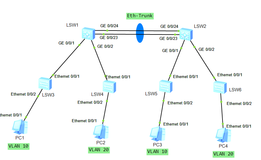
1.1 实验拓扑
1.2 实验要求
- 让两边同VLAN的主机可以互相通信,为了实现冗余和增加带宽,在LSW1和LSW2之间做手工链路聚合。
1.3 实验配置
[LSW1]vlan batch 10 20 //在所有交换机上创建VLAN10和20[LSW2]vlan batch 10 20 //在所有交换机上创建VLAN10和20[LSW3]vlan batch 10 20 //在所有交换机上创建VLAN10和20[LSW4]vlan batch 10 20 //在所有交换机上创建VLAN10和20[LSW5]vlan batch 10 20 //在所有交换机上创建VLAN10和20[LSW6]vlan batch 10 20 //在所有交换机上创建VLAN10和20
将对应的端口划入对应的VLAN[LSW3]int Ethernet0/0/2 //进入E0/0/2端口[LSW3-Ethernet0/0/2]port link-type access //将端口类型改为Access[LSW3-Ethernet0/0/2]port default vlan 10 //将端口划入VLAN 10中[LSW4]int Ethernet0/0/2 //进入E0/0/2端口[LSW4-Ethernet0/0/2]port link-type access //将端口类型改为Access[LSW4-Ethernet0/0/2]port default vlan 20 //将端口划入VLAN 20中[LSW5]int Ethernet0/0/2 //进入E0/0/2端口[LSW5-Ethernet0/0/2]port link-type access //将端口类型改为Access[LSW5-Ethernet0/0/2]port default vlan 10 //将端口划入VLAN 10中[LSW6]int Ethernet0/0/2 //进入E0/0/2端口[LSW6-Ethernet0/0/2]port link-type access //将端口类型改为Access[LSW6-Ethernet0/0/2]port default vlan 20 //将端口划入VLAN 20中
将交换机互联链路配置为Trunk[LSW3]int Ethernet0/0/1 //进入E0/0/1端口[LSW3-Ethernet0/0/1]port link-type trunk //将端口类型修改为Trunk[LSW3-Ethernet0/0/1]port trunk allow-pass vlan 10 20 //Trunk链路允许VLAN10 20的VLAN帧通过[LSW4]int Ethernet0/0/1 //进入E0/0/1端口[LSW4-Ethernet0/0/1]port link-type trunk //将端口类型修改为Trunk[LSW4-Ethernet0/0/1]port trunk allow-pass vlan 10 20 //Trunk链路允许VLAN10 20的VLAN帧通过[LSW5]int Ethernet0/0/1 //进入E0/0/1端口[LSW5-Ethernet0/0/1]port link-type trunk //将端口类型修改为Trunk[LSW5-Ethernet0/0/1]port trunk allow-pass vlan 10 20 //Trunk链路允许VLAN10 20的VLAN帧通过[LSW6]int Ethernet0/0/1 //进入E0/0/1端口[LSW6-Ethernet0/0/1]port link-type trunk //将端口类型修改为Trunk[LSW6-Ethernet0/0/1]port trunk allow-pass vlan 10 20 //Trunk链路允许VLAN10 20的VLAN帧通过[LSW1]int GigabitEthernet 0/0/1 //进入G0/0/1端口[LSW1-GigabitEthernet0/0/1]port link-type trunk //将端口类型修改为Trunk[LSW1-GigabitEthernet0/0/1]port trunk allow-pass vlan 10 20 //允许VLAN10 20的VLAN帧通过[LSW1]int GigabitEthernet 0/0/2 //进入G0/0/2端口[LSW1-GigabitEthernet0/0/2]port link-type trunk //将端口类型修改为Trunk[LSW1-GigabitEthernet0/0/2]port trunk allow-pass vlan 10 20 //允许VLAN10 20的VLAN帧通过[LSW2]int GigabitEthernet 0/0/1 //进入G0/0/1端口[LSW2-GigabitEthernet0/0/1]port link-type trunk //将端口类型修改为Trunk[LSW2-GigabitEthernet0/0/1]port trunk allow-pass vlan 10 20 //允许VLAN10 20的VLAN帧通过[LSW2]int GigabitEthernet 0/0/2 //进入G0/0/2端口[LSW2-GigabitEthernet0/0/2]port link-type trunk //将端口类型修改为Trunk[LSW2-GigabitEthernet0/0/2]port trunk allow-pass vlan 10 20 //允许VLAN10 20的VLAN帧通过
手工链路聚合配置[LSW1]int Eth-Trunk 1 //创建聚合组1[LSW1-Eth-Trunk1]mode manual load-balance //模式修改为手工负载分担[LSW1-Eth-Trunk1]load-balance ? //可以设置负载分担方式dst-ip According to destination IP hash arithmeticdst-mac According to destination MAC hash arithmeticsrc-dst-ip According to source/destination IP hash arithmeticsrc-dst-mac According to source/destination MAC hash arithmeticsrc-ip According to source IP hash arithmeticsrc-mac According to source MAC hash arithmetic[LSW1-Eth-Trunk1]trunkport GigabitEthernet 0/0/23 //将G0/0/23加入聚合组[LSW1-Eth-Trunk1]trunkport GigabitEthernet 0/0/24 //将G0/0/24加入聚合组[LSW1-Eth-Trunk1]port link-type trunk //将聚合组改为Trunk[LSW1-Eth-Trunk1]port trunk allow-pass vlan 10 20 //允许VLAN 10 20的VLAN帧通过[LSW2]int Eth-Trunk 1 //创建聚合组1[LSW2-Eth-Trunk1]mode manual load-balance //模式修改为手工负载分担[LSW2-Eth-Trunk1]trunkport GigabitEthernet 0/0/23 //将G0/0/23加入聚合组[LSW2-Eth-Trunk1]trunkport GigabitEthernet 0/0/24 //将G0/0/24加入聚合组[LSW2-Eth-Trunk1]port link-type trunk //将聚合组改为Trunk[LSW2-Eth-Trunk1]port trunk allow-pass vlan 10 20 //允许VLAN 10 20的VLAN帧通过
1.4 实验结果
PC1访问PC3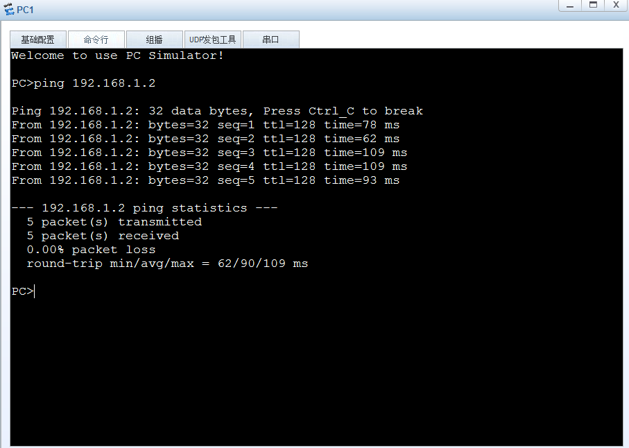
PC2访问PC4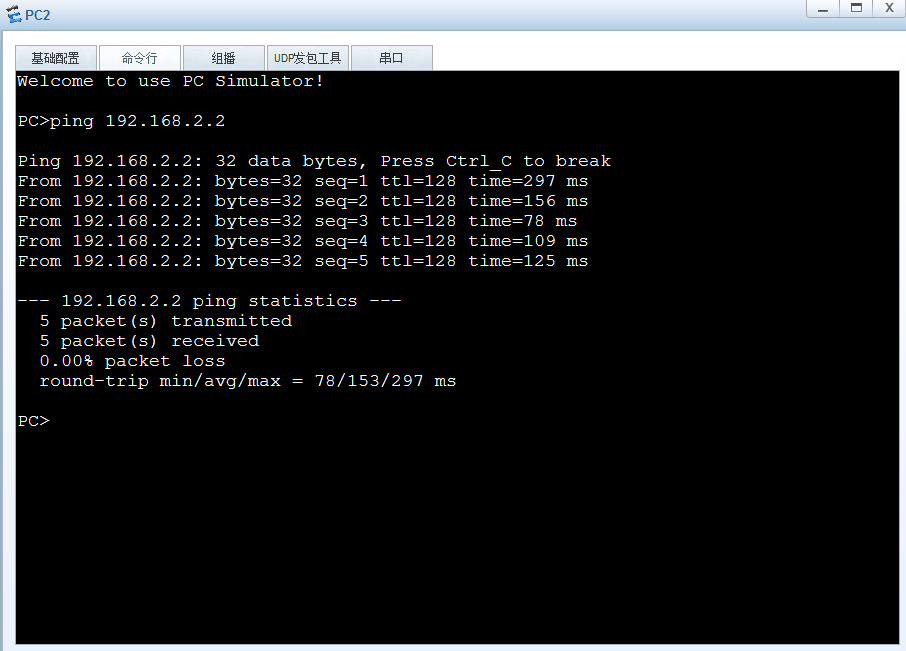
2. LACP链路聚合
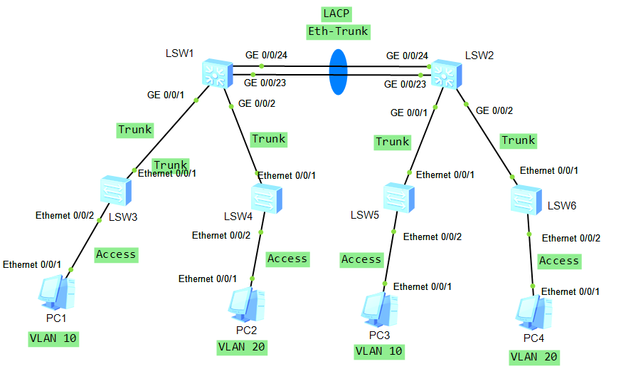
2.1 实验拓扑
2.2 实验要求
- 让两边同VLAN的主机可以互相通信,为了实现冗余和增加带宽,在LSW1和LSW2之间做LACP模式链路聚合。
2.3 实验配置
[LSW1]vlan batch 10 20 //在所有交换机上创建VLAN10和20[LSW2]vlan batch 10 20 //在所有交换机上创建VLAN10和20[LSW3]vlan batch 10 20 //在所有交换机上创建VLAN10和20[LSW4]vlan batch 10 20 //在所有交换机上创建VLAN10和20[LSW5]vlan batch 10 20 //在所有交换机上创建VLAN10和20[LSW6]vlan batch 10 20 //在所有交换机上创建VLAN10和20
将对应的端口划入对应的VLAN[LSW3]int Ethernet0/0/2 //进入E0/0/2端口[LSW3-Ethernet0/0/2]port link-type access //将端口类型改为Access[LSW3-Ethernet0/0/2]port default vlan 10 //将端口划入VLAN 10中[LSW4]int Ethernet0/0/2 //进入E0/0/2端口[LSW4-Ethernet0/0/2]port link-type access //将端口类型改为Access[LSW4-Ethernet0/0/2]port default vlan 20 //将端口划入VLAN 20中[LSW5]int Ethernet0/0/2 //进入E0/0/2端口[LSW5-Ethernet0/0/2]port link-type access //将端口类型改为Access[LSW5-Ethernet0/0/2]port default vlan 10 //将端口划入VLAN 10中[LSW6]int Ethernet0/0/2 //进入E0/0/2端口[LSW6-Ethernet0/0/2]port link-type access //将端口类型改为Access[LSW6-Ethernet0/0/2]port default vlan 20 //将端口划入VLAN 20中
将交换机互联链路配置为Trunk[LSW3]int Ethernet0/0/1 //进入E0/0/1端口[LSW3-Ethernet0/0/1]port link-type trunk //将端口类型修改为Trunk[LSW3-Ethernet0/0/1]port trunk allow-pass vlan 10 20 //Trunk链路允许VLAN10 20的VLAN帧通过[LSW4]int Ethernet0/0/1 //进入E0/0/1端口[LSW4-Ethernet0/0/1]port link-type trunk //将端口类型修改为Trunk[LSW4-Ethernet0/0/1]port trunk allow-pass vlan 10 20 //Trunk链路允许VLAN10 20的VLAN帧通过[LSW5]int Ethernet0/0/1 //进入E0/0/1端口[LSW5-Ethernet0/0/1]port link-type trunk //将端口类型修改为Trunk[LSW5-Ethernet0/0/1]port trunk allow-pass vlan 10 20 //Trunk链路允许VLAN10 20的VLAN帧通过[LSW6]int Ethernet0/0/1 //进入E0/0/1端口[LSW6-Ethernet0/0/1]port link-type trunk //将端口类型修改为Trunk[LSW6-Ethernet0/0/1]port trunk allow-pass vlan 10 20 //Trunk链路允许VLAN10 20的VLAN帧通过[LSW1]int GigabitEthernet 0/0/1 //进入G0/0/1端口[LSW1-GigabitEthernet0/0/1]port link-type trunk //将端口类型修改为Trunk[LSW1-GigabitEthernet0/0/1]port trunk allow-pass vlan 10 20 //允许VLAN10 20的VLAN帧通过[LSW1]int GigabitEthernet 0/0/2 //进入G0/0/2端口[LSW1-GigabitEthernet0/0/2]port link-type trunk //将端口类型修改为Trunk[LSW1-GigabitEthernet0/0/2]port trunk allow-pass vlan 10 20 //允许VLAN10 20的VLAN帧通过[LSW2]int GigabitEthernet 0/0/1 //进入G0/0/1端口[LSW2-GigabitEthernet0/0/1]port link-type trunk //将端口类型修改为Trunk[LSW2-GigabitEthernet0/0/1]port trunk allow-pass vlan 10 20 //允许VLAN10 20的VLAN帧通过[LSW2]int GigabitEthernet 0/0/2 //进入G0/0/2端口[LSW2-GigabitEthernet0/0/2]port link-type trunk //将端口类型修改为Trunk[LSW2-GigabitEthernet0/0/2]port trunk allow-pass vlan 10 20 //允许VLAN10 20的VLAN帧通过
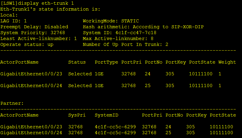
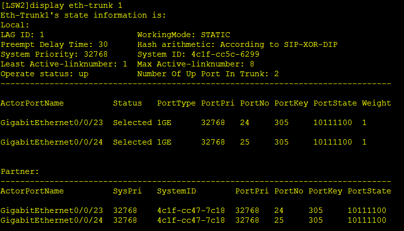
LACP链路聚合配置[LSW1]int Eth-Trunk 1 //创建聚合组1[LSW1-Eth-Trunk1]mode lacp-static //模式修改为静态LACP[LSW1-Eth-Trunk1]load-balance ? //可以设置负载分担方式dst-ip According to destination IP hash arithmeticdst-mac According to destination MAC hash arithmeticsrc-dst-ip According to source/destination IP hash arithmeticsrc-dst-mac According to source/destination MAC hash arithmeticsrc-ip According to source IP hash arithmeticsrc-mac According to source MAC hash arithmetic[LSW1-Eth-Trunk1]trunkport GigabitEthernet 0/0/23 //将G0/0/23加入聚合组[LSW1-Eth-Trunk1]trunkport GigabitEthernet 0/0/24 //将G0/0/24加入聚合组[LSW1-Eth-Trunk1]port link-type trunk //将聚合组改为Trunk[LSW1-Eth-Trunk1]port trunk allow-pass vlan 10 20 //允许VLAN 10 20的VLAN帧通过[LSW2]int Eth-Trunk 1 //创建聚合组1[LSW1-Eth-Trunk1]mode lacp-static //模式修改为静态LACP[LSW2-Eth-Trunk1]trunkport GigabitEthernet 0/0/23 //将G0/0/23加入聚合组[LSW2-Eth-Trunk1]trunkport GigabitEthernet 0/0/24 //将G0/0/24加入聚合组[LSW2-Eth-Trunk1]port link-type trunk //将聚合组改为Trunk[LSW2-Eth-Trunk1]port trunk allow-pass vlan 10 20 //允许VLAN 10 20的VLAN帧通过[LSW1-Eth-Trunk1]lacp preempt ? //配置LACP抢占delay Delay time of preemption //配置抢占延时enable Enable preemption //开启抢占[LSW1-Eth-Trunk1]lacp selected priority //配置自己为主
2.4 实验结果
PC1访问PC3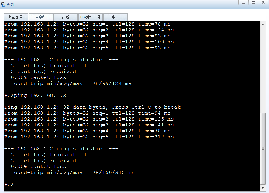
PC2访问PC4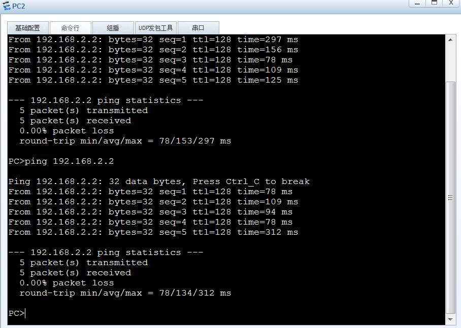

若有收获,就点个赞吧
0 人点赞
